LED light stake


LED light stake
Published 2019-05-14T17:50:57+00:00
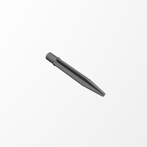
This is a replacement stake I made for one that broke.
It was Designed and uploaded with www.selfcad.com #selfcad #sculp-with-selfcad #selfCADchallenge
I saw the new design comptetition to create a part with a tool called SelfCAD, so I thought I would give it a shot. I will say that even with my limited experience with CAD, it was pretty easy to use.
I started my project by taking some measurements of the light pole that I needed to make a stake for. My next step was to figure out how to visualize the solution I wanted. Fom there I went to SelfCAD and started working.
The first part I added was the easiest, I had the exact measurement from a piece of the old stake so I knew exactly how big a round it needed to be to fit into the light, 21 mm diameter. I created a cylinder at the origin with a 10.5 mm radius, and mat it 30 mm high, which I also measured off the broken stake. I made some guesses on the rest of the stake as it was broken and lost in the ground.
The next step was to add a cylinder 24 mm across and 3 mm tall, this is to simply keep the stake from going all of the way up into the light.
Now for the meat of the project. Although I am not actually making cubes, the name of the tool in SelfCAD is called the cube tool, so I will continue to use that nomenclature, since I am explaining how I designed this in SelfCAD. I created two cubes, to create the main shaft of the stake. They were 24 mm x 3 mm x 100 mm. In retrospect, now that I have reinstalled the light, I could have gotten away with a shorter stake so make 50 mm - 75 mm would have been better here.
The next two cubes I created were to make up the tip of the stake so that it will go into the ground easier. I used two 24 mm x 3 mm x 50 mm cubes, and then I used the taper tool to bring them to a point.
The next step is to use the grouping tool to make all of these components a single 3D part.
Since I am using this to actually install a light outside I want to do a couple of things to make the part stronger. In order to do this it is best to have a part like this oriented so that it lays horizontally and thus reducing the layer adhesion issue filament based printing tends to have.
I mentioned earlier that I could have made the stake a little shorter. I mentioned this as I had to work harder than normal to get the stake into the ground, I could have stopped sooner if the stake had been shorter.


I dd not have to worry about cosmetics as this part was not going to be seen. I made the shells much thicker than I normally do, in this case 1.5 mm. Although, this means most of the part will be solid, there is still a little bit that will contain infill, and I made that infill 70%. My layer lines are thicker, 0.2mm, not my typical 0.1 mm or 0.15 mm I use when making something for looks. And the last thing I did to make it stronger was increase the temperatur of the hotend a bit. Although, it makes things look a little rougher it will increase the adhesion between layer lines. I did need to use supports.
| Date published | 14/05/2019 |