Twilight Zone Mystic Seer


Twilight Zone Mystic Seer
Published 2017-10-20T14:29:08+00:00
News flash! Make sure to check this out: thermal printer upgrade
Small town diner, 1960, somewhere in the Twilight Zone.
Young go-getter William Shatner and his bride find themselves dropping pennies into a fortune telling napkin dispenser, and becoming slowly dependent on the results. While that young couple manage to tear themselves free and live to captain starships, will you be so lucky?
Do you dare face the Mystic Seer?!
This Mystic Seer is as authentically sized to the original as I could determine. Pull the lever, watch the Seer's eyes flash with mystical insight, and receive a ticket that answers your most profound yes/no questions...
Oh, and does it serve napkins? Yes! There are loops on the inside of the napkin holes that are intended to take elastic cord. Lace the cord over the white side panels so that they'll put tension on the napkins once in place. Alternatively, the panels are intended to simply be placed inside the holes, if there's no pressing need for napkin dispensing.
Assembly
Hardware assembly should be pretty apparent from the photos. You will need:
Hardware:
- Four M3 hex nuts to insert into the case body, to hold the electronics mounts.
- 20mm M3 bolt and M3 nylock nut for the lever assembly.
- 9mm x 20mm compression spring for the lever return action.
- Masking tape to wrap around the dispenser wheel for grip on the cards
- Two 9mm x 38mm compression springs for the card dispenser.
- Four 8mm M3 bolts to attach the motor to the dispenser
- Three 6mm M3 and one 12mm M3 bolt to attach the electronics brackets to the case
Electronics:
- 5mm LED for the Seer's illuminated eye
- 13mm diameter press button to be activated by the lever
- An arduino or similar microcontroller board
- Nema 17 motor to dispense cards
- DRV8825 stepper driver or similar
- 100 uF capacitor for the motor wiring
- 10k ohm resistor for the button wiring
- 300 ohm resistor for the LED wiring
- Wires for connectivity
- A power supply for the microcontroller (probably 5V)
- A power supply for the motor (probably 12V)
Now, before you go collecting all those things up, it's worth bearing in mind that I used a 12V stepper with its own power because I already had those lying around. It's undoubtedly easier to just use a 5V motor! Really, the electronics are arbitrary, as long as you can monitor a button, flash an LED, and drive a motor.
Wiring References
So, I was going to put my actual wiring diagram here, but it's probably safer to just link tutorials that will give you the wiring for each element anyway, and avoid the chance that I'll transcribe something wrong, and you'll blow up your board. Or power supply. Power supplies do blow up. Ask me how I know.
Anyway! Where were we?
This is a super-basic tutorial that happens to show how how to hook up a button and make an LED flash. Handy!
https://www.arduino.cc/en/Tutorial/Button
And this shows how to use the DRV8825 to control a stepper motor. However, bear in mind again that point above that it's probably much easier to just use a 5V motor instead! And then you don't end up wiring things up at midnight, accidentally shorting your 12V power supply, and watching smoke come out of it. I assume.
http://www.instructables.com/id/Controll-a-Stepper-Motor-With-the-DRV8825/
Also, I hereby apologise to my electronics friends who tried so hard, and willl probably weep when they see that birds-nest wiring in the photos on this object. I learned nothing :P
Arduino Code
So, the code here is pretty basic. Check the button, flash the eyes, activate the motor. Nothing too crazy. If you're using this code, though, double check what's going on with those stepper definitions! And, of course, make sure the pin assignments do actually mach up with the pins you've chosen in the hardware.
#include <Stepper.h>

const int eyePin = 12;
const int leverPin = 2;
const int dirPin = 8;
const int stepPin = 9;
const int stepperPin3 = 10;
const int stepperPin4 = 11;
const int stepsPerRev = 120;

Stepper dispenser(stepsPerRev, dirPin, stepPin, stepperPin3, stepperPin4);

void setup() {
   pinMode(eyePin, OUTPUT);
   pinMode(leverPin, INPUT);
   dispenser.setSpeed(60);
}

void loop() {
   if (digitalRead(leverPin) == HIGH) {
   // no need to debounce, since this will take a few seconds to execute
   // do some flashy eye stuff
   for (int i=10; i>0; i--) {
       digitalWrite(eyePin, HIGH);
       delay(i*20);
       digitalWrite(eyePin, LOW);
       delay(i*20);
   }
   digitalWrite(eyePin, HIGH);
   delay(1000);
   // push the fortune card
   dispenser.step(2 * stepsPerRev);
   }
}
- - -
Happy Halloween!
This object was made in Tinkercad. https://www.tinkercad.com/things/h5jeA17QMIf


All parts are designed for easy printing. Any overhung parts are made gentle with bevels, and the best print orientation should be fairly apparent with each model.
However, this is a pretty big print! At reasonably good speeds, and with 20% infill, the case alone took 44 hours. Also, the dimensions (being faithful to the original, and all) are such that it only just squeezes in on a 200x300 bed. It would be trivial to split the case parts if you really wanted to, though, since the Tinkercad source is right there and easy to change.
| Date published | 20/10/2017 |
| Tempo per farlo | 50 - Minuti |
| Supporto Gratuito | YES |

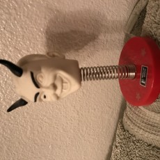
Haven’t printed the box yet but here’s the head.